ESCs to PDB wiring
Mounting the Power Distribution Board and Soldering ESC Wires
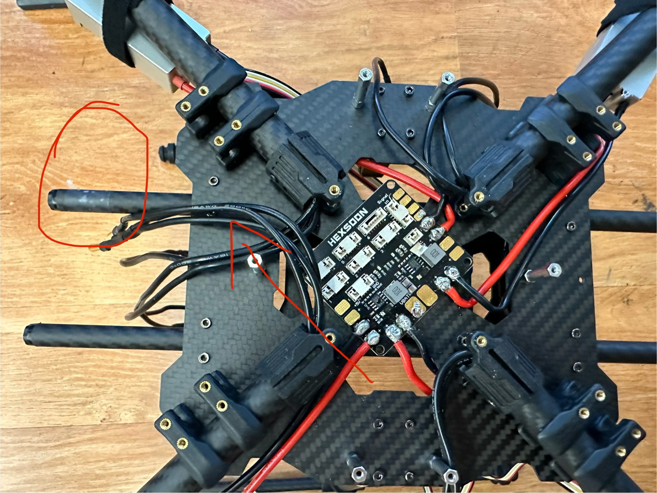
Step 1: Mount the PDB
- Place the PDB on the frame using double-sided tape.
- Use alcohol to clean the contact surfaces first.
- Make sure it faces the correct direction as shown, the "front" is marked by the tape in circle
Important: Use a flat head soldering iron.
Step 2: Wiring the ESCs
- We need to use 8 pads on the PDB for 4 ESCs.
- Follow the scheme below in counter-clockwise (CCW) order.
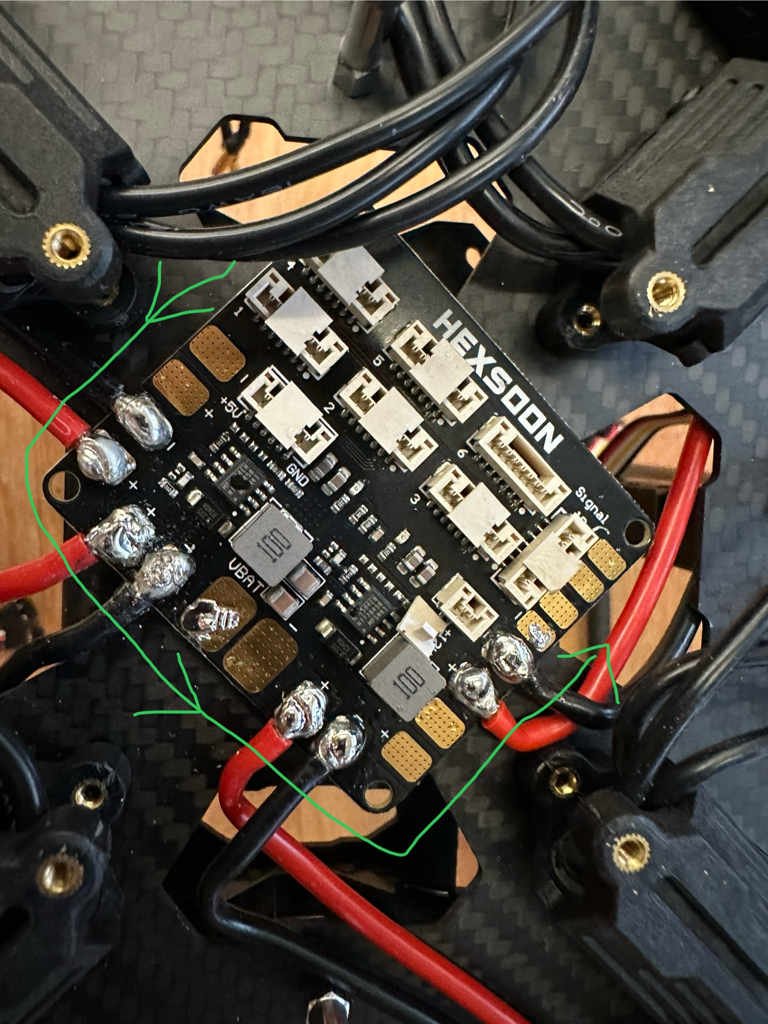
(The complete diagram is below)
- Depending on the specific pad, you may need to pre-bend the ESC wire so it reaches the pad without excess movement.
Step 3: Soldering Procedure
To get a solid connection, follow these steps:
Clean the soldering iron tip using brass wool. Apply a tiny bit of flux if the brass wool doesn’t clean it fully.
Tin the pad:
- Touch the pad with the iron tip and feed in a small amount of solder.
- Hold the tip in place for ~10 seconds until the solder melts.
- Tilt the iron and use the slanted surface to spread the solder and cover the pad.
⚠️ Caution: If pads are not in CCW order, there may not be enough space to lay the iron and use its slanted side.
Place the ESC wire:
- Use tweezers to hold the wire tip on the pad.
- Press the iron tip against it until the solder on the wire and pad both melt.
- If they don’t melt, apply a tiny bit of flux.
Bond the wire:
- Hold the wire in place and lift the iron.
- The wire should stay put as the solder cools.
Reinforce the joint:
- Press the slanted surface of the iron onto the wire again.
- Feed in more solder to fully cover the wire.
- Be careful to avoid solder bridges to other pads or wires.
Cool and check:
- Lift the iron and keep holding the wire with tweezers until the solder cools.
- A good joint will have a smooth and shiny surface.
Test the connection:
- Gently tug the wire to confirm it's solidly bonded.
Repeat for the next pad.
If a connection fails:
- Clean any flux residue on that pad and try again.
- It’s completely normal to not succeed on the first attempt.